

OEM Sampling Valve: A Complete Guide to Selection, Installation, and Maintenance
2026-09-16
When a sampling valve fails in an OEM system, the ripple effect can compromise product quality, delay batch release, and even trigger costly recalls. Yet many engineers still treat these small components as afterthoughts—until a leak or contamination event forces a rethink. This guide cuts through the noise to cover exactly what matters: how to select the right valve for your process, install it without compromising sterility or pressure integrity, and maintain it to avoid unplanned downtime. Along the way, we’ll highlight practical insights from AVM, whose sampling valves have earned a reputation for reliability in demanding OEM applications.
What Actually Matters When Selecting an OEM Sampling Valve
Material compatibility gets overlooked far too often. A valve that handles sterile media in a bioreactor won't necessarily survive aggressive CIP chemicals or high-purity steam. Look beyond the body material—316L stainless steel is common, but elastomers and internal finishes dictate whether you're actually getting a clean, repeatable sample. For aseptic processes, USP Class VI and FDA-compliant seals matter, but so does the surface roughness of wetted parts. Any Ra value above 0.8 µm can create a hiding place for residue or biofilms.
Dead volume is the next non-negotiable. A sampling valve with a large unswept area will give you a sample that doesn't represent the batch—especially after line stops or product changes. Weep grooves, minimal cavity designs, and true zero-dead-leg geometry aren't just marketing terms; they're the difference between a representative grab and a contaminated one. If the valve can't be fully drained or cleaned in place without disassembly, you're adding validation headaches down the road.
Finally, look at how the valve behaves under real operating conditions. Actuation speed, seal wear, and maintenance access matter more than a polished datasheet. Does the supplier offer a documented maintenance kit and clear torque specs? Can the diaphragm or stem seal be replaced without pulling the entire valve from the line? Those details show up after installation, and they're what separate a valve that works for six months from one that works for six years.
Matching Valve Body and Seal Materials to Your Process Media
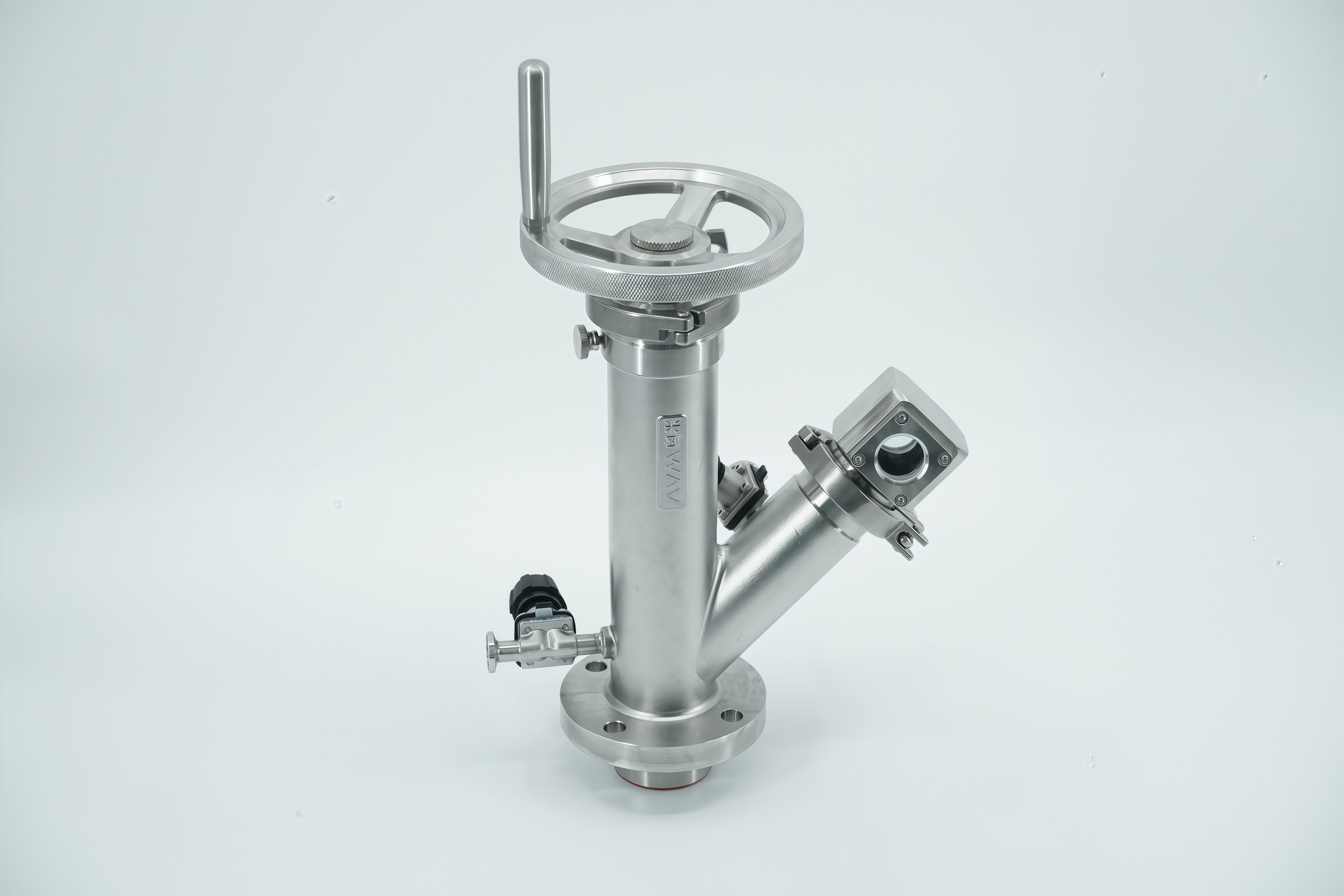
Selecting the right valve body and seal materials isn't just about chemical compatibility charts—it's about understanding how your process behaves under real operating conditions. A material that works fine in a lab test may degrade rapidly when exposed to temperature swings, abrasive particles, or trace contaminants that never show up on a standard datasheet. Start by mapping every chemical in your stream, including cleaning agents, byproducts, and potential impurities. Then look at the concentration ranges and whether any phase changes occur. This deeper dive often reveals that a generic PTFE seal or a 316 stainless body is actually a poor fit for the job.
Once you have the full chemical profile, consider the mechanical and thermal stresses the valve will face. For aggressive acids at elevated temperatures, a fluoropolymer-lined body with a PFA or PTFE seal might seem obvious, but if there are solid particles in the flow, you may need a reinforced seat or a harder seal material like UHMWPE to resist scoring. For steam or hot oils, elastomers like EPDM or FKM can harden and crack, so look to perfluoroelastomers or metal-seated designs instead. And don't overlook galvanic corrosion when body and internal trim are different alloys—sometimes a simple change from a stainless ball to a Hastelloy ball extends service life by years.
Finally, validate your material choice against real field data or a pilot test before committing to a full rollout. Ask vendors for case studies from similar process environments, and if possible, run a coupon test with your actual media at operating temperature and pressure. Remember that seals are often the weakest link—even a highly resistant valve body won't compensate for a seal that swells, dissolves, or loses elasticity under your specific process conditions. By matching both body and seal materials to the true chemistry, temperature, and abrasive character of your media, you avoid unnecessary downtime and replacement costs while keeping the process safe and consistent.
Installation Details That Prevent Leaks and Dead Legs
Getting the connection details right is what separates a system that stays dry for years from one that starts weeping at the joints. Use full-penetration welds where possible, or specify mechanical couplings with restrained gaskets that tolerate slight misalignment without losing compression. Every flange should be torqued in a star pattern, then checked again after the first thermal cycle, because heat expansion works bolts loose in subtle ways. For threaded joints, skip the cheap tape and use a quality anaerobic sealant that fills the thread roots completely—this blocks the micro-channels where slow drips tend to start.
Dead legs form wherever a branch, drain, or instrument tap lets fluid sit with no regular flow. The best fix is to keep any unused stub shorter than one and a half pipe diameters, or better yet, eliminate it during the design review. Where a drain or sample point is absolutely required, angle it downward so it fully empties by gravity, and add a small recirculation line or a timed flush valve if the system runs intermittently. Insulating a dead leg often makes things worse by holding warmth and moisture in place, so leave those short sections uninsulated unless there's a clear condensation risk.
Support placement matters more than most installers admit. A pipe that sags between hangers creates a low point where condensate collects and eventually corrodes through the wall or feeds bacteria. Use engineered guides and anchors to keep the slope consistent, and make sure expansion loops don't create unintended pockets at their lowest ends. After installation, fill the line and walk it with a thermal camera while it's under pressure—odd temperature bands often reveal a hidden dead leg or a slow bypass leak that would otherwise go unnoticed until it becomes a repair ticket.
Creating a Maintenance Routine Around Real Operating Hours
Relying on calendar dates to schedule equipment upkeep often misses the point—what really matters is how many hours a machine has actually been working. Start by pulling hour meter readings, telematics data, or reliable operator logs, then map those numbers against the manufacturer's recommended service intervals. But don't stop there. Look at your own failure history: if a hydraulic pump tends to fail at 1,800 hours instead of the suggested 2,000, set your threshold lower and stop treating the manual as gospel.
Once you have solid hour thresholds for each asset, build ownership into the routine. Assign someone to log hours at the end of every shift, not just when someone remembers. Use a simple spreadsheet, CMMS, or automated alerts tied to telematics—whatever your team will actually stick with. The key is to plan services around anticipated hour accumulation, not a fixed date on the wall. If a machine sits idle for two weeks, its maintenance shouldn't advance. If it runs double shifts, the next oil change might come three weeks early. That's the whole point of tracking real operating hours.
Watch out for the quiet drift that ruins these routines: operators skipping logs, idle time being counted as load time, or seasonal spikes that push equipment past thresholds before anyone notices. Reconcile hour readings against fuel use or job site records once a month, and adjust intervals when a pattern of early wear or unexpected downtime shows up. The goal isn't a perfect schedule on paper—it's a routine that reflects how the machine actually works on the ground.
Signs Your Sampling Valve Is Causing Inconsistent Results
When your process data starts drifting with no corresponding change in upstream conditions, the sampling valve is often the last place anyone looks. You might notice that replicate grabs from the same line show a wider spread than the method's normal variability, or that results swing high and low in a pattern tied to valve actuation frequency. A valve that doesn't fully flush its dead legs between cycles can leave a small but unpredictable carryover from the previous sample, which shows up as phantom shifts in concentration or pH. If you're already running tight controls on temperature and pressure, and the only variable left is the point of extraction, that's a strong clue the valve seat or diaphragm is wearing unevenly.
Other telltale signs are physical and easy to check during a walkdown. Look for a slow drip at the sample port after the valve closes, discoloration around the stem, or a slight resistance change when the handle is moved. These can indicate a seal that is rolling instead of seating cleanly, which lets process fluid leak into the sample stream during collection. You may also find that some operators get consistent results while others don't, which often points to a valve that needs a very specific actuation speed to avoid pulling in stagnant fluid. A quick test is to take three consecutive samples without adjusting the line. If the first one is always an outlier, or if the results tighten up after a manual flush, the valve's internal geometry is likely disturbing the sample before it even reaches your collection container.
Field Testing and Validation Before You Put a Valve Back in Service
You can’t just bolt a rebuilt valve back into the line and hope for the best. Start with a slow, low-pressure stroking test while the valve is still isolated—watch for smooth movement, listen for grinding or hissing, and feel for any stickiness in the handwheel or actuator. If the valve has a position indicator, verify it tracks the actual stem travel. Even a tiny misalignment here can turn into a leak path once full system pressure hits.
After that, run a seat leakage test using the actual service fluid or a compatible substitute, and hold the test pressure long enough to catch slow weepage. Don’t skip the packing gland—adjust it just enough to stop leakage without over-tightening, which can gall the stem. Finally, cycle the valve three to five times under low pressure, then repeat the checks at 50% and 100% of rated pressure. Only when it holds steady and moves cleanly through every step is it worth putting back on the line.
FAQ
Start by matching the valve body and seal materials to your process fluid, temperature range, and cleaning chemicals. Also check the connection standard your existing lines use, and decide whether you need a sterile or sanitary design based on the sampling point's exposure to contamination risk.
A well-supported seat with minimal dead space tends to last longer and is easier to clean in place. Look for designs where the sealing element is not over-compressed during closure, as this reduces wear and prevents particles from being trapped between the seat and the valve body.
Many issues come from misalignment, such as welding the valve into a line under stress or using the wrong torque on clamp fittings. Also, forgetting to remove protective caps until the final connection, or installing the valve in a position where residual liquid cannot drain, can cause corrosion or contamination.
A practical interval is to inspect the seal and actuator every three to six months, depending on cycle frequency and fluid aggressiveness. More important than a fixed calendar schedule is tracking repeated sampling operations and performing a quick visual check after each major CIP cycle.
Yes, if the valve is designed with a clean-in-place or steam-in-place compatible body and seat. The internal flow path must allow full contact with steam or chemical agents, and the valve should be mounted so that condensate drains completely to avoid leaving a wet pocket.
This usually points to a damaged or deformed seal, a scratch on the seat face, or a bent stem from excessive tightening. In some cases, the valve was not fully closed because product residue built up behind the seat, preventing proper seating. Replacing the seal and cleaning the seating area often solves it.
A locking or interlocked handle prevents accidental opening, while a spring-return actuator reduces variability from manual force. Adding a drip leg or a closed sampling container connection also lowers the risk of operator exposure and keeps the sample from being contaminated by the environment.
Conclusion
Selecting an OEM sampling valve often comes down to the details nobody puts in the datasheet. You can have perfect wetted materials and still end up with a valve that traps product, holds cleaning chemistry, or forces operators into risky workarounds. What actually matters is how the valve behaves when it is closed: whether the seal drains fully, whether the body profile creates a dead leg, and whether the sample path can be flushed without disassembling the line. Matching the body and seal materials to the process media is not just about chemical compatibility on paper. Temperature swings, steam cycles, and abrasive particles change how an elastomer or metal performs over time, so the material choice needs to be tested against the worst-case condition you actually run, not the ideal case from a brochure.
Installation details are where most sampling problems begin. The best valve will leak or hold residue if it is mounted with the wrong orientation, unsupported piping, or a ferrule that does not align. A short, self-draining connection and a clear line of sight to the sample point matter more than the valve's pressure rating in many cases. Maintenance also needs to follow real operating hours, not a calendar guess. A valve that cycles fifty times a day will wear seals differently than one used twice a week, so the routine should be built around cycle count, exposure history, and any sign of inconsistent results. If you notice drifting pH, odd particles, or sample volumes that do not repeat, suspect the valve before blaming the analyzer. Finally, no valve should go back into service without a pressure hold test, a flush verification, and a visual check of the seat and seal under actual process conditions. These steps do more to protect sample integrity than any certificate alone.
Contact Us
Contact Person: Ananda
Email: [email protected]
Tel/WhatsApp: 8619016718200
Website: https://www.wzaomi.com