
CNC Parts Manufacturer: Precision Machining for Complex Components
2026-09-23
Ever handed a drawing to a shop and watched a simple-looking part come back with chatter marks, off-center holes, or worse? For complex components, that gap between CAD and finished part is where most manufacturers fail. It’s also where Peak Fasten has built its reputation: precision CNC machining that holds tight tolerances on intricate geometries without sacrificing lead time. Here’s what actually goes into producing those challenging parts—and why the right process matters more than the machine list.
Holding Tolerances Most Shops Won’t Touch
Plenty of shops will quote a job at ±0.005 in and never blink. Ask for ±0.0002 on a bore or a true position under 0.001 and the conversation ends. We pick up those prints on purpose. Holding tight tolerances isn't a side capability here; it's the default setting for the people, fixtures, and inspection room.
The part doesn't care about your reputation. It either fits the mating component or it doesn't. That's why we pre-soak material to let stresses move before finishing, rough in stages, and take final cuts only after the workpiece and spindle have settled. A tenth is not a guess. It's a measurement you have to earn with every setup.
Customers bring us the work their usual vendors returned as 'not manufacturable.' Once we show them the CMM report with every feature green, the conversation shifts from whether it can be done to how many they need next month.
Five-Axis Milling That Cuts Setup Time, Not Corners
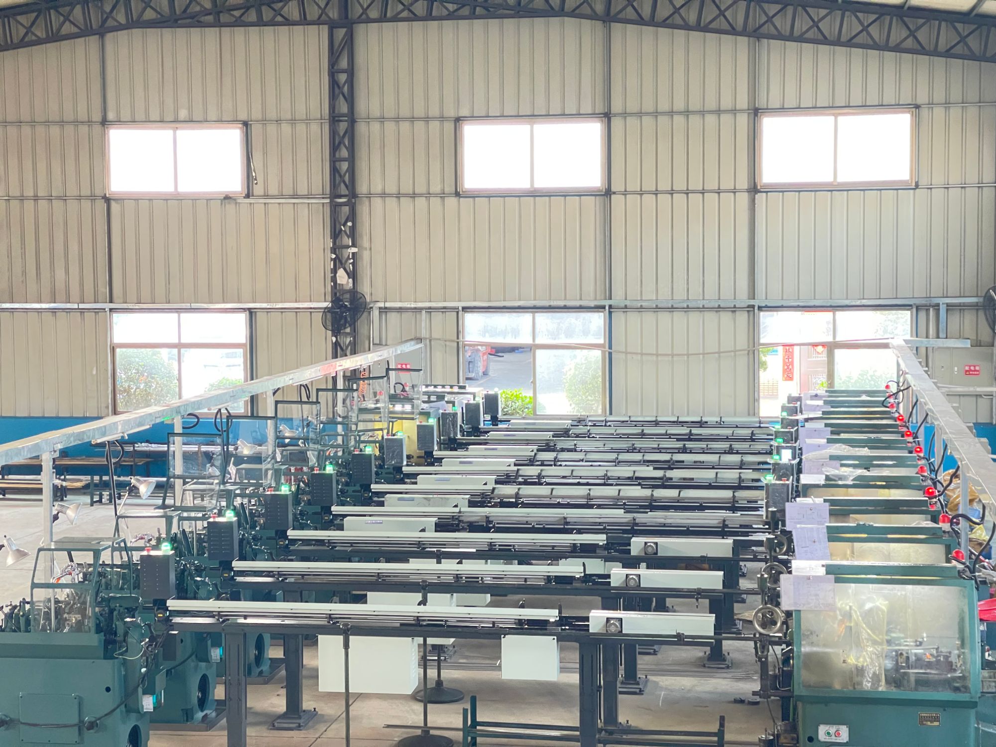
The real bottleneck in complex part production isn't the cutting speed—it's the constant repositioning. Traditional 3-axis machines force you to stop, unclamp, rotate, re-indicate, and re-establish datums for every new face. Our five-axis approach eliminates that dance. The part stays fixed in a single setup while the spindle and table orient themselves around it, reaching undercuts, compound angles, and deep pockets without you touching a clamp or edge finder.
But cutting setup time doesn't mean cutting corners on geometry. We use dynamic work offsets and in-process probing to verify orientation after every rotary move. That means tight true-position tolerances hold across multiple faces without stacking error from manual re-fixturing. The result is fewer scrapped parts, less bench work, and a first article that actually matches the CAD model—not one that's close enough after three tweaks.
For low-volume or prototype runs, this is the difference between a week of fiddling and an afternoon of cutting. Your programmer spends less time building elaborate fixtures, your operator spends less time proving out setups, and your spindle keeps turning. The five-axis machine isn't just a faster tool—it's a simpler workflow that happens to hold tighter tolerances because the part never leaves its reference frame.
Complex Geometries Without the Usual Back-and-Forth
Complex geometries often force teams into exhausting loops of model transfers, file conversions, and redesign requests. A more direct path starts by treating the design and simulation environment as one continuous space, where curvature, lattice structures, and organic forms are defined by parameters rather than hand-built surfaces. This means a designer can specify load cases, material constraints, and manufacturing limits, and the system responds with a shape that already accounts for those conditions. There’s no need to rebuild the model for analysis or wait for a specialist to interpret a mesh. The geometry emerges from the requirements, and each iteration happens in the same native file.
Take, for example, a heat exchanger with twisted internal channels or a bracket with topology-optimized cutouts. In older workflows, each revision would pass through neutral formats like STEP or IGES, losing feature history and introducing tolerance drift. With a unified approach, the parametric definition remains intact: adjust a wall thickness, change a lattice density, or alter an inlet angle, and the downstream simulation and toolpath generation update immediately. This eliminates much of the conversational lag—clarifying emails, annotated screenshots, version confusion—that normally eats into project timelines.
The result is not just faster delivery but a different kind of exploration. Designers can push into regions of complex form that were previously too costly to try, because the penalty for changing direction is so low. Complex geometries become less of a specialist mystery and more of an everyday design option, available at the moment of conception rather than after a long chain of handoffs.
Material Flexibility From Aluminum to Inconel
Ask a machinist about material preferences and you will get a long pause, then a cautious answer about trade-offs. Aluminum cuts like butter but moves under heat. Inconel laughs at your tooling budget. The real skill lies in knowing when each one earns its place on the spindle.
Shops that handle everything from 6061 to 718 have learned to switch strategies on the fly. Aluminum rewards aggressive feeds and sharp geometry, while Inconel demands slower speeds, tougher inserts, and a steady hand on coolant pressure. It is less about having one perfect setup and more about reading how the material fights back.
That flexibility often comes down to machine rigidity, tooling inventory, and the operator's instinct for chip color and sound. A shop that can move from soft gummy alloys to hardened superalloys without flinching offers more than a list of capabilities. It offers a way to keep complex projects under one roof.
In-Line Metrology Keeps Every Feature Honest
In-line metrology does what a final inspection room cannot: it measures a feature while the cutting tool is still close, the coolant is still warm, and the part has not yet been unclamped. That timing matters. A bore checked five minutes after machining may have already relaxed a few microns. A bore checked in the fixture catches the true machined condition. When every critical dimension—diameter, position, profile, runout—is captured at the moment of creation, there is no room for a feature to drift out of tolerance and hide behind a favorable post-process reading.
The honest part is not just about catching bad pieces, though. In-line metrology creates a feedback loop that post-process sampling never could. If a probe detects that a tool is wearing and a shoulder is creeping toward its upper limit, the controller can adjust offsets or swap the tool before the next part ever loads. That turns inspection from a gatekeeper into a process control. Features don't just get verified; they get kept honest in real time, part after part, with no batch of scrap building up between checks.
Consider a complex casting or a machined manifold with dozens of bores, seats, and sealing faces. In a traditional setup, you might measure a few samples per shift and hope the rest follow. In-line metrology scans every feature on every unit, or at least every critical one, while the workpiece is still fixtured. Thermal expansion, clamping distortion, tool deflection—all the usual liars—are measured and accounted for on the spot. The result is a part that matches its drawing when it matters: before it leaves the cell, not after a lab report arrives two hours later.
DFM Feedback Before the First Chip Is Cut
Waiting until silicon returns to uncover manufacturability issues is a luxury few design teams can afford. Modern DFM feedback loops bring lithography checks, pattern density analysis, and via reliability assessments directly into the layout phase, letting engineers catch hotspots while edits are still cheap.
The real value appears when this feedback is treated as a design partner rather than a final gate. Subtle problems like metal fill interfering with sensitive analog blocks or dummy structures shifting critical capacitance become visible in the virtual fab long before masks are ordered. Designers can then adjust routing, tweak cell placement, or rebalance fill without derailing the schedule.
By the time the first chip actually reaches the fab, the design has already survived thousands of simulated process corners. That doesn't guarantee first-pass success, but it removes the avoidable surprises—and turns DFM from a post-layout chore into a continuous conversation with the manufacturing line.
FAQ
Dimensional tolerances typically stay within ±0.005 mm, and tighter values are possible for specific features once we review the geometry and material. Each project starts with a feasibility check on critical dimensions so the quoted range is actually repeatable in production.
We work with aluminum alloys, stainless steels, titanium, engineering plastics, and some high-temperature alloys. Material selection includes the part's load, temperature, and exposure conditions, so we often suggest alternatives when a spec creates unnecessary machining risk.
Yes, we move from single-piece prototypes to medium batches in the thousands. Process parameters and inspection records from the prototype phase carry directly into production, which cuts down first-article adjustments and keeps lead times predictable.
Complex geometries are usually machined in one 5-axis setup to avoid errors from repositioning. In-process checks and CMM or optical measurements on each batch help us trace any deviation back to tool wear or clamping before it affects more parts.
Common options include anodizing, bead blasting, passivation, plating, PVD coating, and precision polishing. We leave controlled stock on mating or cosmetic surfaces so post-processing does not push final dimensions out of tolerance.
We accept STEP or IGES files, but we also flag features that are difficult to machine, such as sharp internal corners, deep threads, or poor clamping areas. Small changes suggested early can greatly improve stability and reduce cost without changing the part's function.
Most of our work comes from medical devices, robotic joints, optical instruments, drone propulsion, and semiconductor test fixtures. These parts often combine thin walls, deep cavities, or freeform surfaces, which suits our approach to complex machining.
Conclusion
Most machine shops will politely decline work that calls for ±0.0002 inches on a bore or a true position within a few microns. We take those jobs on purpose. Holding tolerances most shops won’t touch is less about having the right machine and more about understanding thermal drift, tool deflection, and the sequence of cuts that keeps a part stable. Pair that with full five-axis milling and you get something rare: parts that come off the table with fewer setups, less handling, and no sacrifice to squareness or blend. Instead of transferring a part from vise to vise and stacking error at every step, five-axis lets us reach five sides in one clamping, which means the complex geometries stay true to the model without the usual back-and-forth about feasibility or rework loops.
The material range matters just as much as the machine. Aluminum cuts easily but moves; Inconel work-hardens if you look at it wrong; stainless likes to soak up heat and warp. We adjust speeds, feeds, and toolpath strategy for each, rather than forcing a one-size-fits-all process. In-line metrology keeps every feature honest by probing critical dimensions while the part is still on the machine, so a drifting bore or a shifting wall gets caught before the next operation. And none of that means much if the design is fighting the manufacturing process from the start. That’s why we give DFM feedback before the first chip is cut: we flag thin floors, deep pockets, and impossible corner radii early, suggest alternatives that hold the same function, and then machine a part that actually matches the print. It’s a tighter loop than most buyers are used to, and it saves both time and scrap.
Contact Us
Contact Person: Mason Lv
Email: [email protected]
Tel/WhatsApp: +86 13027998452
Website: https://www.peakfastentech.com